GPU cluster architecture: how the system fits together
A model spread across two GPU workers depends on both servers and the network between them. Its placement shapes the GPU communication path, the model-loading process, and recovery after a worker failure. Defining the GPU cluster architecture before deployment connects the capacity datacenters and neoclouds supply with the production requirements inference providers must meet.
What is a GPU cluster?
A GPU cluster is a group of GPU-equipped servers, called nodes, coordinated through networking and software to run accelerated workloads. Graphics processing units (GPUs) perform the parallel calculations. Central processing units (CPUs), host memory, storage, and the control layer keep them supplied with data and assign their work.
A cluster can run many independent inference replicas or spread one job across several nodes. Those are different architectures. Connecting servers does not automatically combine their GPU memory into one larger device. The application needs a distributed execution strategy to use that memory across devices.
We design our fully managed clusters around this whole system, covering architecture, deployment, and end-to-end operations. Our clusterdOS engine is the open-source engine inside each cluster. The important starting question is what the workload needs from the cluster, including its behavior when part of the infrastructure is unavailable.
Decide which work crosses the server boundary
There are three common reasons to use multiple GPUs: fit a larger workload in memory, finish a job sooner, or serve more requests. They lead to different communication patterns.
| Workload shape | How work is divided | Architecture consequence |
|---|---|---|
| Independent inference replicas | Each replica holds its own model and handles separate requests | Request routing, per-replica memory, model loading, and spare serving capacity lead the design |
| A model distributed across GPUs | Tensor parallelism splits each layer’s tensors, weights, and computation across GPUs; pipeline parallelism splits model layers | GPU-to-GPU communication becomes part of request execution, within a node or across nodes |
| Distributed training | Workers process data and synchronize gradients or other training state, with the exact pattern set by the framework | Collective communication, dataset delivery, and checkpoint recovery all affect useful scaling |
For inference, keep a replica within a single GPU or node when that meets its memory and performance requirements. Distributing a model across servers adds a communication dependency to that replica. The vLLM inference engine's parallelism guidance distinguishes single-GPU, single-node, and multi-node execution, including combinations of tensor and pipeline parallelism. These are placement choices, not universal GPU-count thresholds.
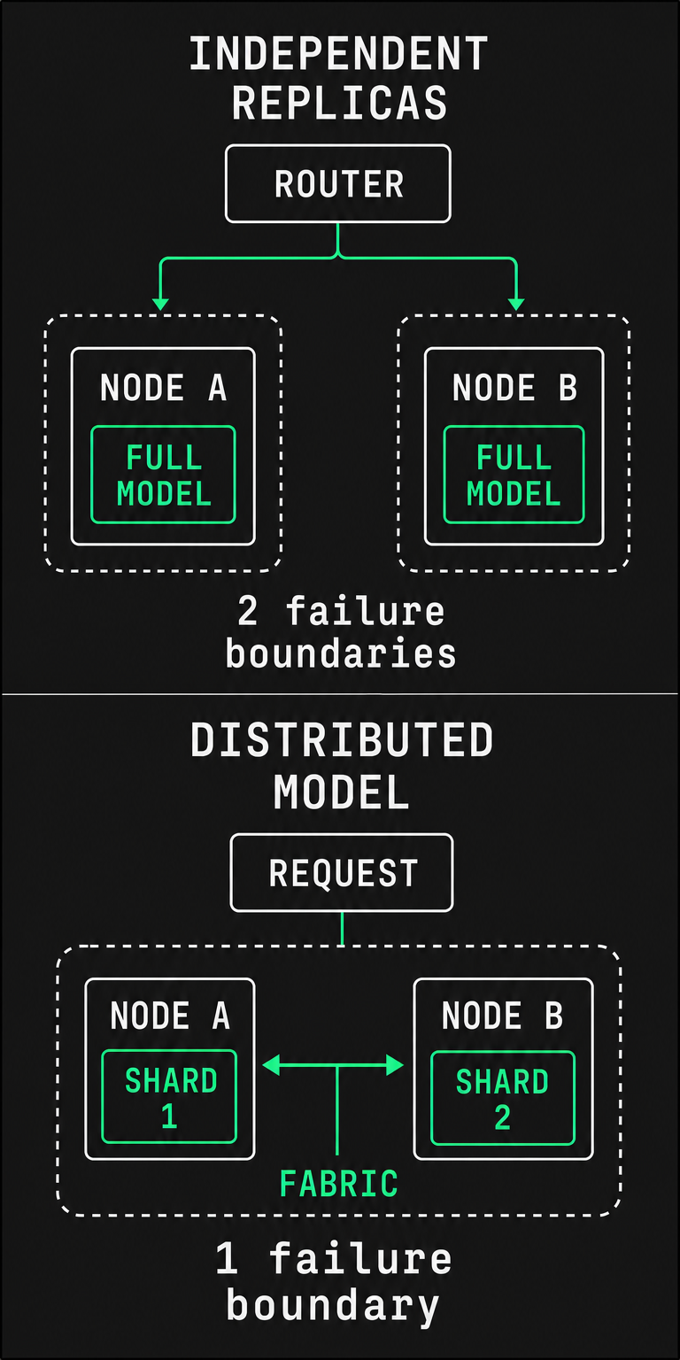
The failure boundary changes with placement. If one model spans two workers, losing either worker interrupts that model instance. Two independent replicas on separate workers have a different recovery path, provided the remaining replica has enough capacity. The same GPU count can therefore represent very different service resilience.
The workload specification should name the model or training revision, precision, memory requirement, concurrency, input and output lengths, and performance target. Include model-loading and recovery expectations. GPU count alone cannot supply those answers.
The architecture connects five responsibilities
Compute executes the workload. The fabric moves data between devices and servers. Storage supplies durable artifacts and working data. Software allocates and maintains the system. Validation establishes whether those parts deliver the intended result together.
Traffic roles are logical. Physical switch counts, cabling layouts, and configuration support depend on the chosen hardware and workload.

Compute: size the working unit, including memory
A worker contains more than accelerators. Its CPUs handle host-side execution and data preparation. Host random-access memory (RAM) holds application data and staging buffers. Local NVMe, a fast flash-storage interface, can cache model files and datasets. Network interface cards, or NICs, connect that worker to the rest of the cluster.
GPU memory must accommodate the workload's live state. For inference, that includes model weights, runtime allocations, and the key-value cache, which stores attention state for active requests. Longer contexts and more concurrent requests can change the memory requirement even when the model stays the same.
Illustrative hardware assumption: two vendor-qualified x86 servers, each containing eight NVIDIA H100 80 GB board-mounted (SXM) GPU modules, NVSwitch switches linking the GPUs, local NVMe, and qualified NIC placement. Three separate CPU nodes host the Kubernetes control plane, the services that coordinate cluster state and workload placement. Assume an InfiniBand compute fabric and distinct storage and management traffic roles. This is an architecture example, not a sizing recommendation or a measured deployment.
NVIDIA's DGX H100 specifications illustrate why the full node matters: eight H100 GPUs provide 640 GB of aggregate GPU memory, alongside separate system memory, cache storage, and compute and storage network interfaces. Aggregate memory is an inventory total. An application still needs an appropriate parallelism strategy and space for its other allocations.
For mixed hardware, create distinct worker pools with explicit GPU type, memory, interconnect, and software compatibility. A scheduler's ability to place work on either pool does not make their performance interchangeable.
Fabric: distinguish device links from cluster networks
A fabric is the connected set of links and switches carrying traffic. Start by separating its jobs:
- Within the worker: PCI Express (PCIe) connects server devices. NVLink connects GPUs, with NVSwitch routing traffic between those links on applicable systems. Their topology determines the available GPU-to-GPU and GPU-to-NIC paths.
- Between workers: InfiniBand or Ethernet carries distributed GPU communication. RoCE, RDMA over Converged Ethernet, provides remote direct memory access over Ethernet. RDMA lets compatible devices move data with less CPU-managed copying.
- To storage: a storage path carries weights, datasets, and checkpoints. Its traffic can compete with workload communication if they share constrained links.
- For control and recovery: in-band management carries host and cluster services. Out-of-band management reaches hardware controllers independently of the host OS, so operators can recover a server whose operating system has failed.
These are logical responsibilities. Some designs use separate physical networks; others share infrastructure with explicit capacity, isolation, and congestion policies. NVIDIA's GB200 network architecture demonstrates that distinction: storage and in-band management share an Ethernet fabric, while compute and out-of-band roles use other physical fabrics. It also includes multi-node NVLink, so “NVLink always stops at one server” is an unsafe generalization.
For the H100 worker example, NVLink/NVSwitch serves the GPUs inside each node, and the inter-node compute fabric connects the workers. A high advertised NIC rate does not establish end-to-end bandwidth. Switch uplinks, concurrent traffic, device placement, and the transport available inside the workload container all matter.
InfiniBand needs a subnet manager, the service that configures the fabric's addressing and routes. RoCE needs coordinated NIC and switch congestion settings. NVIDIA's fabric diagnostic guidance distinguishes these requirements.
GPUDirect RDMA allows a compatible NIC to access GPU memory directly. It requires a compatible hardware and software path; an RDMA-capable switch alone is insufficient. NVIDIA's GPU-to-NIC requirements describe the driver and memory-sharing mechanisms involved.
Storage: design for cold starts and recovery
Storage has two distinct roles: retaining data and delivering it quickly enough. Durable storage holds model artifacts, datasets, and recoverable checkpoints. Local caches reduce repeated reads, but disposable cache contents cannot be the only copy of required data.
An inference cluster can run well with warm caches and still recover slowly when replacement workers start empty. A training cluster can compute quickly and then stall while writing checkpoints. Capacity in terabytes does not describe either behavior.
A useful planning floor is:
Required aggregate payload rate = bytes needed by all concurrent readers ÷ allowed transfer time.
For example, eight new replicas each loading 120 GB of uncached weights in 90 seconds require about 10.7 GB/s of aggregate payload delivery. This is a calculated example, not an observed result or a complete startup estimate. Protocol overhead, storage contention, deserialization, and initialization add work beyond that transfer floor.
Choose object, file, or block access according to the workload's interface and concurrency needs. Specify concurrent cold-load time, checkpoint write and restore time, and the behavior of a failed storage path. Fast local disks do not resolve a bottleneck in the durable source.
Software: connect hardware enablement to workload placement
The software stack has several responsibilities:
| Responsibility | What it supplies |
|---|---|
| Host lifecycle | Repeatable OS images, firmware baselines, kernel configuration, updates, and replacement-node provisioning |
| GPU enablement | Drivers, GPU access inside containers, device discovery, and health telemetry |
| Orchestration | Resource allocation, placement, service or job lifecycle, and access policy |
| Workload runtime | GPU-compute libraries, distributed communication, and the inference engine or training framework |
| Operations | Logs, metrics, alerts, configuration history, backups, and recovery procedures |
Kubernetes orchestrates containerized workloads. Slurm allocates resources and queues batch jobs. Virtual machines provide a separate execution boundary. These can occupy different roles in one environment; the decision follows the workload and operating model.
In a conventional Kubernetes GPU deployment, vendor drivers and a device plugin make GPUs available as schedulable resources. Kubernetes documents this GPU resource model. Advertising a GPU does not establish that a multi-node workload has the right network devices, storage access, or placement.
Illustrative software assumption: Ubuntu 24.04 LTS, Kubernetes 1.36, containerd 2.3.6, NVIDIA GPU Operator 26.7.2, and NVIDIA driver 595.91.07. Containerd runs the containers; GPU Operator coordinates GPU-enablement components. Containerd's release and compatibility tables identify 2.3 as a maintained long-term-support branch and recommend that branch, starting at 2.3.0, for Kubernetes 1.36. NVIDIA's platform support matrix includes Ubuntu 24.04 with Kubernetes 1.33–1.37, containerd 2.0–2.3, and the listed Operator and driver versions. These documents establish family-level support and runtime recommendations. They do not certify this exact full stack, its performance, or Aranya support for the combination.
The deployment specification also needs exact OS, kernel, and Kubernetes patches, firmware revisions, container image digests, and the versions of CUDA, NVIDIA's GPU-compute platform, and the communication libraries used by each workload. A digest identifies fixed image contents. Separate hardware pools may need separate qualified profiles.
For the H100/NVSwitch example, that profile includes NVIDIA Fabric Manager 595.91.07, the service managing the NVLink fabric. This pre-620 driver requires a matching Fabric Manager package version. Qualification also includes driver hardware caveats: with driver 595.91.07, Hopper subrevision 3 needs VBIOS, the GPU firmware, 96.00.68.00.xx or newer to initialize.
Prerequisites are architecture decisions with owners
Before implementation, each layer needs a defined requirement and an accountable owner. A datacenter supplies facility and hardware facts; the cluster operator translates them into usable resources; the inference provider defines the service behavior. One team can hold several roles, but none can remain implicit.
| Area | Required input before the build | Why it matters |
|---|---|---|
| Compute and facility | Hardware inventory, workload memory and GPU requirements, sustained power and cooling capacity, and replacement capacity | Establishes what can run and what remains available during maintenance or failure |
| Networking | Device and switch topology, traffic roles, addresses, routes, name resolution, time synchronization, and required transport | Establishes the paths the workload and control services depend on |
| Storage | Durable data locations, access interface, concurrent read/write demand, cold-load target, and restore target | Connects storage sizing to startup, steady-state work, and recovery |
| Software | Qualified version manifest, provisioning inputs, workload images, scheduler model, authorized access, and upgrade ownership | Makes workers reproducible and compatibility changes accountable |
| Validation | Fixed workload definition, performance and recovery thresholds, test scope, and the person accepting the result | Gives “production-ready” a measurable meaning |
Physical installation and adequate facility capacity are prerequisites to software deployment. A reachable host or a populated inventory does not establish workload readiness. Build-ready means the architecture decisions and implementation inputs are available, with acceptance criteria already agreed.
Validation closes the architecture loop
Validation belongs in the design because its results can change the design. A service that misses its latency target after a worker fails may need more reserve capacity, a different placement boundary, or a different recovery objective.
Use separate evidence for separate claims:
- Hardware health: every expected GPU and device is present, with acceptable thermal behavior and no unresolved hardware faults. NVIDIA Data Center GPU Manager (DCGM) provides monitoring and online diagnostics. Its diagnostic scope does not replace full offline hardware validation.
- Data-path behavior: the intended GPU, NIC, switch, and storage paths meet bandwidth and latency requirements under concurrent load. A successful ping establishes reachability, not the performance of direct GPU-memory transfers.
- Scheduled execution: the production scheduler launches the intended workload image with the expected GPUs, network access, and storage mounts. For distributed work, the expected processes participate in their intended communication groups, with the expected membership for each group.
- Workload and recovery: the real application meets its targets during sustained operation, cold starts, and the agreed failure scenarios.
NVIDIA's Collective Communications Library, NCCL, implements communication operations across GPUs. Its official collective test suite measures correctness and performance. A good collective result establishes a communication baseline; it does not establish inference latency, model quality, or training throughput.
For inference, acceptance should fix the model revision, precision, engine version, request-length distribution, and concurrency. Measure request errors, throughput, time to first token, and tail latency, such as p95 and p99, the values below which 95% and 99% of observations fall. For training, specify step time, data-loading stalls, checkpoint duration, and successful restoration.
Keep the failure scenarios tied to dependencies. Removing a worker exercises a different boundary from losing a storage path or the whole facility. Three control-plane nodes cannot supply missing GPU capacity. Two replicas cannot absorb a failure if both already need their full capacity to serve normal traffic. Our inference reliability guide separates failures inside a cluster from failures affecting an entire datacenter.
Choose who owns the cluster and the fleet
A scheduler is one component of the operating model. Someone still owns driver compatibility, network faults, storage recovery, hardware quarantine, upgrades, and the on-call response.
Our open-source clusterdOS engine is Kubernetes-based and provides the inside-cluster operating layer. It extends to virtual machine (VM) and Slurm environments. Aranya OS is our proprietary multicluster operating system. It builds on clusterdOS to federate clusters into one fleet, operating within and across clusters. Each cluster retains its local fabric and failure boundaries; fleet coordination does not turn the network between facilities into a local GPU interconnect.
We deliver this through fully managed clusters, covering architecture, deployment, and end-to-end operations, or through self-managed software operated by the customer, currently in private alpha. These are delivery modes, with different ownership of operations. They are not separate operating systems.
For shared customer infrastructure, workload separation needs an explicit security design. A Kubernetes namespace groups resources for management. Namespaces and GPU allocation alone do not establish tenant isolation; Kubernetes' multi-tenancy guidance calls for controls across access, networking, storage, and workload isolation. For managed operations, we act only on access the customer explicitly grants, with role-based permissions for each person.
Move from architecture to implementation
The handoff into deployment should contain the workload specification, topology, version manifest, data paths, operating owners, and acceptance thresholds. Once those decisions are settled, our GPU cluster build procedure covers provisioning, fabric and storage bring-up, GPU enablement, and acceptance in implementation order.
If you have GPU, CPU, and storage hardware already racked and ready, talk to an engineer about a custom cluster designed and operated around your workload.
